


Forms and Surfaces
Basis in OpenGL
The basic mechanisms to create forms in OpenGL is very simple. If we boil everything down to the most basic command we end up with one drawing primitive, glVertex:
glVertex(x,y,z)
The basic principle in OpenGL is that we may set a lot of state variables and thereby control series of calls to this simple, one-point, drawing primitive. The first we may do is to establish the state polygon by framing a series of vertexes, by glBegin() and glEnd() , and thereby telling OpenGL to interpret the enclosed vertexes as a polygon. For instance:
glBegin(GL_POLYGON)
  glVertex(x1,y1,z1)
  glVertex(x2,y2,z2)
  glVertex(x3,y3,z3)
  ...
  glVertex(xn,yn,zn)
glEnd()
The parameter in glBegin() describes how the following sequence of point should be interpreted:
| GL_POINTS | GL_POLYGON | GL_QUADS |
|---|---|---|
 |
 |
 |
| GL_TRIANGLES | GL_TRIANGLE_STRIP | GL_QUAD_STRIP |
 |
 |
 |

OpenGL can not handle convex polygons in a safe way. Safe in the sense that OpenGL can always find out which polygon should completely or partly hide an other polygon in a 3D-scene. The reason for this is that it is that the cost of correct depth sorting is much higher for concave polygons. You may specify concave polygons but the result is not guaranteed.
We also know that polygons with more than three corners may be curved in he sense that the corners not necessarily is on a plane.
Quadrics
OpenGL has some auxiliary routines that draw "standard" shapes, known as quadrics. These routines are placed in the glu-library. Routines in glu are based on primitives gl-routines and are introduced to help us do common things more simple.
The forms are sphere, cylinder and disc. we may control some of the properties of these forms through parameters. Some examples:
 glShadeModel(GL_SMOOTH); gluSphere(qd,2.0,15,15); |
 glShadeModel(GL_FLAT); gluSphere(qd,2.0,15,15); |
 glShadeModel(GL_SMOOTH); gluCylinder(qd,2.0,2.0,2.5,15,15); |
 glShadeModel(GL_FLAT); gluCylinder(qd,2.0,2.0,2.5,15,15); |
 glShadeModel(GL_SMOOTH); gluCylinder(qd,2.0,0.0,2.5,15,15); |
 glShadeModel(GL_SMOOTH); gluDisk(qd,1.0,2.0,15,15); |
 gluQuadricDrawStyle(qd,GLU_LINE); gluSphere(qd,2.0,10,10); |
 gluQuadricDrawStyle(qd,GLU_LINE); gluCylinder(qd,2.0,0.5,2.5,5,5); |
We can combine these standard forms, and may with some creativity make a lot of useful, animated or static, illustrations in 3D.
 Bjørn Stærks bicycle trip Download and run (windows exe-file):sykkel.exe |
 Table top |
 House |
General data structures
OpenGL is basically a routine library and has not defined any data format for geometrical descriptions. It would have been nice to move models from 3D drawing programs to OpenGL in a simple and flexible way. We might for instance want something like: loadFigurFromFile() and renderFigur(). There is of course nothing that stops us from making such routines ourselves, with the flexibility we would like. There are how ever a few complications we meet when we try to do so. Since OpenGL is a "state machine" we would have to set correct states, in addition to the rendering itself. We would for instance have to know if the points we render are specified clockwise or counterclockwise. This would define what is inside and what is outside of a form.
There are some more or less well defined standards for transporting 3D-shapes. Some have their origin i certain products and some are attempts to make general standards. VRML (Virtual reality Modeling Language) [2] and its successor X3D [3] is such standards.
If we should approach this problem it may be interesting to see what we could achieve with the simplest form possible, triangles. All forms should be describable with triangles, and they have the nice property that they have the same normal in each corner (since they define a plane). The following extract from a data set describes a shape made in old 3D Studio MAX. The lines show which corners are associated to a triangle, and the last lines shows the coordinates of the corners:
  indexes to trianglecorners
  0, 13, 12,
  0, 1, 13,
  1, 14, 13,
  1, 2, 14,
  ...
  286, 11, 10,
  286, 287, 11,
  287, 0, 11,
  287, 276, 0

  corners
  69.3 5.89 0,
  63.4 16.1 0,
  53.2 22 0,
  41.5 22 0,
  ...
  34.7 -19.7 -9.31,
  45.7 -22.8 -12.3,
  56.7 -19.7 -15.2,
  64.8 -11.4 -17.4
The data above is in VRML-format, and are describing the following form:

You may inspect the complete file here: torus. You could try to make a routine that extracts the data necessary for creating the the form in OpenGL. You may run the file in your browser if you have a plugin that handles VRML installed. If not you will only see the source.torus.wrl.
Data based
Often we get the data we should model from measurements, typically points in a 3D coordinate system, maps from the surface of the earth, from under seas explorations or from samplings of many kinds. Examples are maps of meteorological data, pollution, medical data or whatever. Such data must almost always be treated in some way before they are presented. We may want to do one or more of the following operations: filtering, smoothing, color coding.
The illustrations below is from a case with smoothing:


Functions
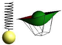
We can always look for mathematical functions that produce 3D shapes, z=f(x,y). The drawing below shows a sinus:

f(x,y)=h·sin(pi·x/n)sin(pi ·y/n).
Even if we may conclude that we are close to a mediaeval head garment, we will probably fast find out that it is not easy to find general functions , in the form z=f(x,y) that suits our needs.
It is far more useful to make surfaces based on polynoms in a parametric form:
	x(t)=fx(t)
	y(t)=fy(t)
	z(t)=fz(t)
We let the parameter t run in small steps and calculate the coordinates (x,y,z). The functions f are polynomials of some order. By deciding some constraints, and the order of the polynomials, we can describe almost any shape we want. See the modules:Bezier and NURB.
The Bezier surface and the NURB below are based on this.
Bezier
Bezier surfaces, see module Bezier is a simple and fast way to describe surfaces. The illustration shows a symmetrical surface with lines connecting the 16 control points.

Bezier surfaces can be described with many control points, and thus a high order polynomial. It may be inconvenient numerically with very high order polynomials, so the alternative is to connect a number of surfaces, where each is fairly simple.
NURB
Non Uniform Rational B-splines, see module NURB is a more flexible method for surface descriptions. We may work with larger surfaces and we can control the smoothness simpler than with connected Bezier surfaces. The illustration below is from a case modeling water..

Some techniques
Rotation
We can describe surfaces by rotating a contour round an axis. The illustration below is based on a contour which is a cubic Bezier curve


Extruding
We simply "stretch" a contour in a direction.


Flipping
When we want to model some shape which is symmetrical, we can often model only half the shape, flip 180 degrees and draw again.
 |
It is not possible to describe an egg form with a standard quadric, but it is fairly simple to describe a half-egg with a Bezier function. The illustration shows an egg based on two half eggs. The control points for one half is shown. |
Clipping planes
Clipping planes is a useful tool. We can at any time during the rendering set up clip planes that cuts off parts of a shape.
 |
This illustrations shows the egg, with each half-egg drawn 4 times and with two clipping planes. |
The Teapot

|
A classic in Computer Graphics is "The Utah Teapot". [4] |
