

Shadow
Shadows are an important characteristic for how we perceive the world. It helps us to judge an object's form and characteristics, and it is also a decisive factor to decide depth and distance to what we see. Even though we don't give too much thought to what shadows really mean for our comprehension of the surroundings, we would immediately notice that a 3d scene without shadows lacks life and realism. This is why calculation of shadow is a very important means to create a believable copy of the real world in 3d graphics.
When I started my work on this module I thought it would be easy to find lots of material about a seemingly central topic in 3D graphics. There are admittedly a good amount of code examples on the Internet, but these are most of the time poorly commented and the solutions for the shadow problem are proprietary. For this reason much of my work with this module has consisted in gathering and reading theoretical material about shadow casting in OpenGL. I feel that this module is just as important as the code examples I have made for the subject. I have tried to gather information about different ways to attack the problem, and to give an overview of these on this page. I have tried to make the web page I would have liked to read when I started on this assignment.
Important knowledge
It can be important to have some basic knowledge about OpenGL before you start on shadow in this module. Basic subjects are: Transformations, planes and textures.
Beyond that there is much useful to be found in the book: "OpenGL Programming Guide"
[1].
These chapters have been particularly useful when developing this module:
Chapter 6: Blending, Antialiasing, Fog and Polygon Offset
Chapter 9: Texture Mapping
Chapter 10: The Framebuffer
I addition I have had to find much documentation about the subject on my own. Some sources are OpenGL for Java [2] , NeHe(OpenGL tutorial) [3] , nVidia [4] . A lot of articles and white papers are references at the bottom of the module.
Three main strategies for shadow in OpenGL
As mentioned earlier shadows are an important means to create realism in a three-dimensional scene. But as with other areas in OpenGL we have to consider the conflict between quality/realism and performance. It is important with a basic understanding of the part that light plays when we are casting shadows. Because of this it is an advantage to study light in OpenGL before you start with calculation of shadows. As with light we have the possibility for increasing levels of realism when it comes to shadow, but this is often at the expense of the performance when rendering a scene.
OpenGL does not have direct support for shadows, but there are several ways to implement shadow functions with the existing library. Implementing these methods vary in difficulty, and quality of the result. We can say that the quality of a shadow varies as a function with two parameters. The complexity of the object that is casting shadow and the complexity of the object that the shadow falls on.
There are three main strategies to make shadow in OpenGL, projection shadows, shadow volumes and shadow maps. Inside these three strategies there are many levels of detail, depending on how advanced knowledge of OpenGL one has.
Projection shadows
Projection shadows are a simple way to implement shadow in an OpenGL scene. An object is projected on to a plane, which is then rendered as a separate object.
I will use a very simple example on a projection shadow. We'll imagine that we have a plane, a triangle and a light source.

When the triangle is between the plane and the light source we will get a shadow on the plane. The question is how we can find the shape and placement of the shadow on the plane. We imagine vectors that start at the light source, go through the corners on the triangle and continue until they cut through the plane. To find the point where the vectors pierce the plane, there are some assumptions we have to make.
For x1,x2 and x3 this gives us:
A line L through a point p = (p1,p2,p3) and with the same
direction as a = [a1,a2,a3] is the collection of all
points x on the form: x = p + t·a.
(1)   x1 = p1 + t·a1
      x2 = p2 + t·a2
      x3 = p3 + t·a3

An equation for a plane is:
(2)   n1·r1 + n2·r2 + n3·r3 + d = 0
      where the plane's normal n = [n1,n2,n3]
      and has a arbitrary  point in the plane r = (r1,r2,r3).

To find the point on line L that lies in the plane
we have the relation:
(3)   n1(p1 + t·a1) + n2(p2 + t·a2) + n3(p3 + t·a3)=
      n1·r1 + n2·r2 + n3·r3

We find t:
(4)   n1·p1 + n1·t·a1 + n2·p2 + n2·t·a2 + n3·p3 + n3·t·a3 =
      n1·r1 + n2·r2 + n3·r3

      n1·t·a1 + n2·t·a2 + n3·t·a3 =
      n1·r1 + n2·r2 + n3·r3 - n1·p1 - n2·p2 - n3·p3

      t(n1·a1 + n2·a2 + n3·a3) =
      n1(r1 - p1) + n2(r2 - p2) + n3(r3 - p3)

      t = (n1(r1 - p1) + n2(r2 - p2) + n3(r3 - p3))/
      (n1·a1 + n2·a2 + n3·a3)

We can now put t into the equation (1) to
find x1, x2 and x3.
These are the coordinates for a point in the plane on a straight line L that runs through the point p (the object casts a shadow) and that has a direction vector a (the direction of the light).
This means that to find the shadow that a triangle casts on a plane we need the following: The points that are being projected on to the plane, a vector describing the direction of the light. If the light is "infinitely" far away (direction), all of the light's vectors will be parallel when they hit an object. This gives us only one point (for example p1) and the direction vector for the light. But if the light has an exact placement (positional) every vector from the light will have a different direction through a point. In this case we have to calculate the direction vector for every line L that runs through the points in the triangle and pierces the plane. In my code example I have used a directional light as a starting point. We also need the equation for the plane to find where in the room the line L pierces the plane.
Screen shot from simpleshadow.java

The code for simpleshadow.java:
simpleshadow.java
Texture used for the program:
marblefloor.png
In the application I have used these methods to calculate the normal to the plane and the projection:
//Find the normal for a plane based on three known points in the plane
public float[] calculateNormal(float p1[],float p2[],float p3[])
{
   float normal[] = new float[3];

   //The normal can be found given two vectors (three points) in the plane

   normal[0] =
   (((p2[1]-p1[1])*(p3[2]-p1[2]))-((p2[2]-p1[2])*(p3[1]-p1[1])));

   normal[1] =
   (((p2[2]-p1[2])*(p3[0]-p1[0]))-((p2[0]-p1[0])*(p3[2]-p1[2])));

   normal[2] =
   (((p2[0]-p1[0])*(p3[1]-p1[1]))-((p2[1]-p1[1])*(p3[0]-p1[0])));

   return normal;
}
//A method that calculates the parameter called t from a given point on a given
//surface and with a directional vector that equals the direction of the light.
//r is a given point in the plane, p is the point we want to project, n is the
//plane's normal and a is the direction vector of the light.

public float[] calculateProjection(float r[], float p[], float n[],
   float a[]){

   float projection [] = new float[3];

   //Calculate t
   float t =
   (n[0]*(r[0] - p[0]) + n[1]*(r[1] - p[1]) + n[2]*(r[2] - p[2]))/
   (n[0]*a[0] + n[1]*a[1] + n[2]*a[2]);

   //Puts t into the equation (1)
   float x1 = p[0] + (t * a[0]);
   float x2 = p[1] + (t * a[1]);
   float x3 = p[2] + (t * a[2]);

   projection[0] = x1;
   projection[1] = x2;
   projection[2] = x3;

   return projection;
}
Then I render the projection points as a new object with the desired colors and properties for a shadow. To avoid stitching I use a polygon offset which is well commented in the code.
Comments for simpleshadow.java
I had no experience with programming OpenGL when this course began. To get a feeling of the mathematics and different calculations that is behind transformations among other things in OpenGL, I chose a basic approach in this application. Because of this I haven't used the possibilities implemented in OpenGL with regard to "Viewing and Modeling Transformations" and matrix multiplication ("glMultMatrixf(...)"). I have implemented the methods I needed myself to get a better understanding of what is happening. The code may seem a bit "heavy" as I haven't used some of the built in methods in OpenGL.
Advantages and disadvantages with projections shadows
This method for creating shadows is limited by several factors. To begin with it's difficult to use this method when we need to cast shadow on more complex objects than surfaces. It is possible to project on an object built from polygons by finding every polygon's plane equation, before "clipping" the shadow in accordance to the polygons' limits. Some times depth buffering can be used for this. When we have a model that only consists of floor and walls as in simpleshadow, this method is acceptable.
Another problem with this method is controlling the color of the shadow. Since the shadow is a "compressed" version of the object that casts the shadow, the shadow's normals will be affected. This leads to consequences for lighting and other properties of the shadow.
Since I didn't project the shadow with help from matrix multiplication in simpleshadow, I avoided the last problem. The shadow is an independent object calculated with regard to the rules that apply for projection. The shadow's normals have not been manipulated, and so I can set the desired material properties on it. The next example, where I use matrix multiplication, will on the other hand contain this problem.
Projection shadows with stencil
In the simpleshadow application I used an approximation for projection shadow where I ran all translations and rotations myself to be able to keep the different coordinates for the triangle. It is easier to achieve this effect by using a known algorithm for projections on planes. This algorithm is easy to implement and is suitable for all cases where an object shall cast a shadow on to a known plane.
Shadow matrix
If you have the equation for a plane and the position for the light, you can construct a 4x4 shadow matrix (planar projected shadow matrix). This projects 3D polygons to a specified ground plan based on the light's position. By transforming a polygonal object with the shadow matrix, all of the object's polygons are "stacked" on the ground plan and creates a shadow effect. You can think of this shadow as a "pile" of projected polygons without height.
So we have to make a shadow matrix to then multiply it with the modelview matrix. The shadow then gets its color, is rasterized and then placed on the ground plane by simply rendering the object once more.
The algorithm for the shadow matrix is well known. My implementation of it looks like this:
//The function return a 4x4 shadow matrix, and receives two arrays that
//contains the plane function for a plane that we will cast shadow on
//and the position of the light.
public float[] shadowMatrix( float plane[], float light_pos[]) {
       float shadow_mat[] = new float[16];
       float dot;

	   //Finds dot, which is the product of the light vetcor and the plane's normal
       dot = plane[0] * light_pos[0] +
        plane[1] * light_pos[1] +
        plane[2] * light_pos[2] +
        plane[3] * light_pos[3];

       shadow_mat[0]  = dot - light_pos[0] * plane[0];
       shadow_mat[4]  = -light_pos[0] * plane[1];
       shadow_mat[8]  = -light_pos[0] * plane[2];
       shadow_mat[12] = -light_pos[0] * plane[3];

       shadow_mat[1]  = -light_pos[1] * plane[0];
       shadow_mat[5]  = dot - light_pos[1] * plane[1];
       shadow_mat[9]  = -light_pos[1] * plane[2];
       shadow_mat[13] = -light_pos[1] * plane[3];

       shadow_mat[2]  = -light_pos[2] * plane[0];
       shadow_mat[6]  = -light_pos[2] * plane[1];
       shadow_mat[10] = dot - light_pos[2] * plane[2];
       shadow_mat[14] = -light_pos[2] * plane[3];

       shadow_mat[3]  = -light_pos[3] * plane[0];
       shadow_mat[7]  = -light_pos[3] * plane[1];
       shadow_mat[11] = -light_pos[3] * plane[2];
       shadow_mat[15] = dot - light_pos[3] * plane[3];

       return shadow_mat;
}
Plane equation
We notice that we have to know the equation for the ground plane on the form ax + by + cz + d = 0 to be able to use the shadow matrix. This can be found with this method:
//Find the plane on the form ax +  by + cx + d,
//based on three known points in the plane
//p1, p2, p3. a,b,c is the plane's normal.
public float [] calculatePlane(float p1[],float p2[],float p3[]){
	//Array for the plane equation
    float plane[] = new float[4];

	//Given two vectors (three points) in the plane
	//the normal can be calculated
    plane[0] = ((p2[1]-p1[1])*(p3[2]-p1[2]))-
                             ((p2[2]-p1[2])*(p3[1]-p1[1]));
    plane[1] = ((p2[2]-p1[2])*(p3[0]-p1[0]))-
                             ((p2[0]-p1[0])*(p3[2]-p1[2]));
    plane[2] = ((p2[0]-p1[0])*(p3[1]-p1[1]))-
                             ((p2[1]-p1[1])*(p3[0]-p1[0]));
    plane[3] = -(plane[0]*p1[0] + plane[1]*p1[1] + plane[2]*p1[2]);


    return plane;
}
To draw a shadow of an object on a floor the code would look something like this in buffershadow. The coordinates to the floor (floor[][]) are a two-dimensional array. We have declared the arrays plan_floor[] with 4 elements and shadow_floor[] with 16 elements globally as well.
public void init() {
         .......
         .......

	//Finds the plane for floor based on three known points
    float plane_floor[] = calculatePlane(floor[1],floor[2],floor[3]);
	//Makes shadowMatrix for the floor
    shadow_floor = shadowMatrix(plane_floor,light_position);

         .......
         .......
}
For simplicity I have chose not to describe some of the methods I use to draw shadow in buffershadow. You can study these in the source code. In this example we are now able to draw a floor, an object and shadow on the floor like this.
public void display() {
            .......
            .......

       //Draws the floor
       gl.glPushMatrix();
         drawFloor();
       gl.glPopMatrix();

	   //Draws a shadow of an object on the floor
       gl.glPushMatrix();
         gl.glMultMatrixf(shadow_floor);
         drawObject();
       gl.glPopMatrix();

       //Draws the object
       gl.glPushMatrix();
         drawObject();
       gl.glPopMatrix();

            .......
            .......
}
Double Blending
There is however a couple of problems connected to this method, except the obvious weakness that objects only can cast shadow on known planes. The shadow is placed in the same plane as the ground plane. This leads to stitching of the shadow with the plane since their depth values will be approximately the same. A way to solve this is by using polygon offset. To get a realistic shadow we want to blend the shadow with the material properties of the plane we are casting the shadow on to. This is not very simple. The problem is that when the shadow matrix projects an object's polygons on to a plane, the pixels will be updated more than once. This means that a particular pixel in the shadow is blended several times, and the shadow becomes too dark in the current point. This problem is known as double blending. Here is an example on how this can look.

Stencil Buffer
We will now have a look on how we can improve projection shadows with help from stencil buffer. Both double blending, limitation of shadow to a plane's area and stitching can be solved with use of stencil buffer. The idea with this method is to give a unique non-zero value for pixels that belong to a ground plane (or the plane we want to cast shadow on). The code examples are a little different from the code used in buffershadow. I have simplified them to make it easier to follow. If you are interested you can study the source code.
  gl.glEnable(GL_STENCIL_TEST);
  gl.glStencilFunc(GL_ALWAYS, unique_stencil_value, ~0);
  gl.glStencilOp (GL_KEEP, GL_KEEP, GL_REPLACE);
  drawPlane();
  gl.glDisable(GL_STENCIL_TEST)

  //Only want to update pixels that have a unique_stencil_value
  //and reset to zero when the pixel's stencil value
  //is updated.
  gl.glDisable(GL_DEPTH_TEST);
  gl.glEnable(GL_STENCIL_TEST);
  gl.glStencilFunc(GL_EQUAL, unique_stencil_value, ~0);
  gl.glStencilOp(GL_KEEP,GL_KEEP,GL_ZERO);

  //Turn blending on
  gl.glEnable(GL_BLEND);
  gl.glBlendFunc(GL_src_ALPHA, GL_ONE_MINUS_src_ALPHA);
  //Turn of light to draw shadow without normals
  gl.glDisable(GL_LIGHTING);
  //Exsisting color (on plane) is modulated with 50% black
  gl.glColor4f(0.0f,0.0f,0.0f,0.5f);

  //Draw shadow of objects on the floor
  drawObject();

  //Restore original mode
  gl.glDisable(GL_BLEND);
  gl.glDisable(GL_STENCIL_TEST);
  gl.glEnable(GL_DEPTH_TEST);
  gl.glEnable(GL_LIGHTING);
It will only be pixels that are associated with the unique stencil value of the ground plane that are updated when the shadow is rendered. Blending is turned on, but to avoid double blending when a pixel is updated, the stencil has to be reset to 0 to make the following pixel updates fail the stencil test and get eliminated.
Another advantage when using stencil buffer is that the use of polygon offset becomes redundant. The depth test is turned off during the stencil based rendering of the projected shadow.
buffershadow.java
The program's buffershadow demonstrated use of stencil buffer to cast shadow on three different planes, floor and two walls. A screen shot from the program buffershadow.java.

The code for buffershadow.java:
buffershadow.java
Textures used in the program:
kommode_front.png
kommode_texture.png
wood_light.png
Comments for buffershadow.java
As mentioned earlier the method in which you use the projection matrix to cast shadow is limited to
planes. This results in that we have to find the equation for every plane in the object we want to shade,
when we want another object to cast a shadow on it.
Because of this the object cannot be very complex, and it has to consist of defined planes. If we
are being picky the table in buffershadow should have cast shadow on the upper chair's seat.
This is possible, even though it isn't implemented in buffershadow, it can be done by keeping the
modelview matrix at different stages with glGetFloatv(GL_MODELVIEW_MATRIX, modelview_matrix).
We could have found the points for the seat and calculated the different planes and shadow matrices
and then render a shadow on the seat. But as we can see it can be very many calculations in a scene with
many complex objects. So you would have to consider other methods to cast shadow in scenes.
Methods for shadows on complex objects are described later in the module.
By rotating the scene we see that the objects' shadows are drawn on the back of the floor and the walls.
In a scene that can't be rotated this is not a problem, since the shadows on the back will not
be visible. Another, which may be a bit coarse way to solve this, is to draw double walls,
this way the new planes covers the shadows.
Soft Shadow
By adding a function for rendering the shadow several times and with a small translation for each rendering, we can achieve a soft shadow. The method to do this is commented out in buffershadow, since it requires a great deal of processing power to do this. The program uses a bit of time to start on an average computer. If you want to you can remove the comment tags in the marked places. This is a screen shot from buffershadow.java where the jitter function is activated.

We put every rendering of the shadow in the accumulation buffer, and then draw the final result. The method to do achieve this effect can be implemented in gl4java like this:
public void display() {
  .......
  .......

  float dx,dy,dz;
  dx = -0.2f;
  dy = 0.0f;
  dz = -0.2f;

  gl.glClear(GL_ACCUM_BUFFER_BIT);
  for (int i = 0; i<4; i++){
    dz+=0.1f;
    for (int j = 0; j<4; j++){
      dx+=0.1f;
      drawScene(dx,dy,dz);
      gl.glAccum(GL_ACCUM, 1.0f/16.0f);
    }
  }
  gl.glAccum(GL_RETURN, 1.0f);

  .......
  .......
drawScene executes the rendering and receives the parameters dx, dy and dz.
public void drawScene(float dx, float dy, float dz) {
  //The buffers needs to be emptied for every rendering
  gl.glClear(GL_COLOR_BUFFER_BIT |
             GL_DEPTH_BUFFER_BIT |
             GL_STENCIL_BUFFER_BIT);

  //Draw plane
  gl.glPushMatrix();
  drawPlane();
  gl.glPopMatrix();

  //Draw shadow. Is translated with given parameters for
  //every rendering of the jitter code.
  gl.glPushMatrix();
    gl.glMultMatrixf(shadow_floor);
    gl.glTranslatef(dx,dy,dz);
    drawObject();
  gl.glPopMatrix();

  //Draw object
  gl.glPushMatrix();
    drawObject();
  gl.glPopMatrix();
Extension of algorithm for projections shades.
Variations and extensions of the method I have described in this section can be implemented. It often desired to have several objects that cast shadow on several planes. It could also be several light sources in the scene that creates more shadows from each object.
I would like to refer to the pdf document "Improving Shadows and Reflections via the Stencil Buffer"
by Mark J. Kilgard from the NVIDIA Corporation. In this document you find very good explanations
and suggestions for implementing different shadow methods.
The document also contains some examples on how to realize the different methods and algorithms
in OpenGL code.
The document is available on the nvida site.
You can download the pfd file if you follow this link:
stencil.pdf
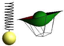
Shadow Volumes
With use of shadow volumes every object that casts a shadow will create an area in the space we define as Volume. Stencil Buffer is then used to find the intersection point between objects in the scene and the shadow. See figure below.

Shadow Volume is constructed by rays from the light source (Ray Tracing) that intersect the corners in the object that casts a shadow, and then continues on out of the scene. This gives us a polygonal surface that contains objects that is shaded or partially shaded. Stencil buffer is used to calculate what part of the objects that is inside the shadow volume. For every pixel in the scene the stencil value will be increased if the border for the shadow volume is intersected on the way into the shadow, and decreased if the border is intersected on the way out. The stencil operation is set to only increase or decrease when the depth test is passed. The result of this is that all the pixels in the scene with stencil values not equal to zero will identify the parts of an object that is inside the shadow.
Since the shape of the shadow volume is decided by the corners of the object that casts the shadow, it is possible to construct complex shadow volumes.
The algorithm for a simple object casting a shadow and a light source can be described like this:
1.  Color buffer and depth buffer is opened for writing and depth testing
	is activated.
2.  Set attributes for drawing in shade. Turn off light source.
3.  Render the whole scene.
4.  Find the polygons that are inside the shadow volume.
5.  Turn off color and depth buffer for writing,
    but keeps depth test active.
6.  Set the stencil buffer to 0 if the eye is
    outside the shadow volume, 1 if it is inside.
7.  Set the stencil function to always to pass.
8.  Set the stencil operation to increase if
    depth test passes.
9.  Turn on back face culling.
10. Render the shadow volume polygons.
11. Set the stencil test to decrease if depth test passes.
12. Turn on front face culling.
13. Render shadow volume polygons.
14. Set the stencil function to test if
    the value is 0 (equal)
15. Set the stencil operation to do nothing.
16. Turn on lighting.
17. Render the scene.
When the scene is rendered for the second time, only pixels with a stencil value equal to 0 are updated. Since the stencil value only was changed when the depth test passed, this value represents how many times the pixel's projection passed inside the shadow volume less the number of times it passed outside the shadow volume before the closest object in the scene was "hit". If the border has been crossed an even number of times the pixel's projection has "hit" an object outside the shadow volume. This is why the pixels on the outside of the volume can "see" the light, and is also why the light is turned on before the last rendering off the scene.
When there are complicated objects that are going to cast shadow in a scene it is sensible to find the points that describes the object's silhouette and use these in the calculation of the shadow volume. This can be a comprehensive task when the objects are very complicated.
Advantages and disadvantages with shadow volume
The algorithm can easily be extended to include several light sources in a scene. For every light source we repeat the second "round" of the algorithm, set the stencil buffer to 0, calculate the shadow volume and render to update the stencil buffer. Instead of replacing the pixel value for objects that are outside any shadow, we choose an appropriate blending function and turn on the current light.
The problems with this method occur when the object that casts a shadow is very complex, and thus difficult makes it difficult to calculate the right shadow volume. The method also requires thorough knowledge about the use of stencil and depth buffer.
Shadow Maps
Shadow Maps uses depth buffer and texture projection to create shadow in a scene. The scene is transformed to put the eye in the same position as the light. The objects in the scene are rendered and the depth buffer is updated. This gives us "the light's depth buffer", and is what we call a shadow map. The shadow map is used for placing textures on the region in the shadow.

The algorithm for shadow maps can be described as follows:
The algorithm requires two renderings:
1. The first rendering
  1. Render the depth buffer from the position of the light in the space
     (The result is a shadow map that is used in the 2. rendering)

2. The second rendering
  1. Render the scene from the position of the eye in the space. For every fragment
     that is converted to a window coordinate (Rasterized):
	  - Find the fragment's XYZ position in relation to the light
	  - Compare the depth value for the light's position XY in the depth map
		with the fragment's light position Z

  2. A = Z value from the depth map with the fragment's XY light position
     B = Z value for the the fragment's XYZ light position

  3. If B is larger than A there has to be "something" that is closer to the light than
     the current fragment
      - The fragment is shaded

  4. If A and B are close to equal the fragment is outside the shadow
Advantages and disadvantages with shadow maps
Shadow maps have a big advantage since the method doesn't depend on finding the silhouette for the objects that are casting shadow. Nor is it necessary to clip the result of the shadow. Every object that can be rendered can throw shadow with shadow maps.
Since a shadow map is made up of points we can get a problem with aliasing. When the texture is placed, is it not sure that the form of the original shadow texel fits with the pixel. This can result in "jagged looking" borders for the shadows. We can also experience objects that cast shadow upon them.
A special case arises when we have a light source surrounded by objects that are going to cast shadow. It is very difficult to implement the shadow map technique in this scene since we create shadow maps by rendering the scene seen from the light's position in space. But in this case it will be difficult to find an appropriate way to do this. We have to render the scene 360 degrees around the light, which isn't a trivial matter.

)
)
)
)