
Plane
Plane
If we know two vectors that form an angle which is not equal to 0 or 180 degrees, the plane spawn by the two vectors is uniquely defined. This means that if we know three points that are not on a line, the plane is uniquely defined. The plane's normal is defined by the two vectors cross product.

The general form for a plane is
Ax+By+Cz+D=0
where the vector |A B C| is the plane's normal. We will not prove or deduce or give reasons for this. Notice that we use the right hand rule to calculate the normal. This is important when we are stating normals in OpenGL. Since OpenGL separates between front and back on surfaces, it is important that we state normals in a systematic way. D can be found by inserting a point in the plane in the general plane equation.
Lets study some examples:
Example 1.

Assume P1 =(0,0,0), P2=(2,0,0) and P3=(0,3,0)
N=P1P2 X P1P3= [2,0,0] X [0,3,0]
= [0·0-0·3 , 0·0-2·0 , 2·3-0·0]
= [0,0,6]
The plane: 6z+D=0.
Substitute for P1, and get 0+D=0, which gives D=0.
The plane equation becomes 6z=0, or z=0.
Example 2.

Assume P1 =(0,1,0), P2=(1,0,0) and P3=(0,0,1)
N=P1P3 X P1P2= [0,-1,1] X [1,-1,0]
= [-1·0-1·(-1),1·1-0·0
,0·(-1)-(-1)·1]
= [1,1,1]
The plane: x+y+z+D=0.
Insert for P1, and get1+D=0, which givesD=-1.
The plane equation becomes x+y+z-1=0
Plane and line
We will try to solve the general problem with finding the intersection between a line through the points O and Q and a plane described by P1, P2 and P3. We assume that P1, P2 and P3 are not on a line, which makes us sure that the three points describe a plane.

We assume that we have found the plane equation as shown above:
Ax+By+Cz+D=0
We can relate this problem to the problem of calculating shadows. A corresponding analysis is useful to understand ray tracing. We imagine that O is the position of the light source, and that Q is the corner of a surface that are going to cast shadow on the plane. For simplicity we place the light source in origin, which means that O is origin. This does not make it less general since we know that we can transform to a random origin.
The line from origin through Q can be described parametric like this:
P=t·Q
or for every component:
x=t·xQ
y=t·yQ
z=t·zQ
Our problem is reduced to finding the t-value where the line intersects with the plane. We insert into the plane equation and get:
A·t·xQ+ B·t·yQ+ C·t·zQ+ D=0
Solved with regard to t:
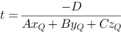
We'll find the line's intersection point with the plane, expressed with Q and the plane coefficients.
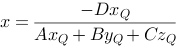
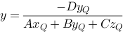
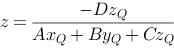
Notice that the plane equation does not inform us about the boundaries of the plane. Thus there is no information in the expression above that tells us if the intersection point is inside a limited polygon in the plane.
We will study the expression above a bit more. We want to express the connection between the intersection point and Q in a matrix form. If we can do this, we could use the following strategy to draw a polygon and its shadow onto a plane.
   // draw the polygon
   DrawPolygon(p)
   < create a transformation matrix based
     on the plane equation >
   // draw shadow
   DrawPolygon(p)
The question now is what the transformation matrix should look like. It should realize the connection between Q and the intersection point, P, between the line from origin through Q and the plane.
The connection above can be expressed like this in a matrix:
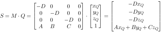
For this to be right we must assume that the result vector is homogeneous, that means that the first three coordinates are divided with the last. See Homogeneous Coordinates. This is how it works in OpenGL, and we can realize a drawing strategy as sketched above.
   DrawPolygon(p)
   float m={...}
   glPushMatrix()
   glMultMatrix(m)
   DrawPolygon(p)
   glPopMatrix()
Shadow is discussed in the module Shadows.
Clipping planes in OpenGL
OpenGL gives us an opportunity to create (temporary) clipping planes while drawing a figure. If we for example want to draw a half sphere, we can use a clipping plane that "slice" the sphere and draws half of it.
Creating a clipping plane is done with the function glClipPlane:
glClipPlane(GL_CLIP_PLANEi, coefficients that describe the plane);
The constant GL_CLIP_PLANEi tells us that we are using clipping plane i. i is a number in the area [0..n] that controls the n+1 possible clipping planes. n should be at least 5 in an OpenGL implementation.
The coefficients that describe the plane are A, B, C, D as planes are described above.
An example of drawing a half sphere:
double clip_plane1[]={0.0,0.0,-1.0,0.5};
gl.glClipPlane(GL.GL_CLIP_PLANE1,clip_plane1,0);
gl.glEnable(GL.GL_CLIP_PLANE1);
// drawing a sphere
GLUquadric qd=glu.gluNewQuadric();
glu.gluSphere(qd,3.0f,20,20);
glu.gluDeleteQuadric(qd);
gl.glDisable(GL.GL_CLIP_PLANE1);
|

|
Notice that the individual clipping planes has to/can be turned off and on.
