
Spatial transformations

|
This means that if I put my right hand vertically down, like in karate, with my fingers along the positive x-axis, and bend the hand towards the y-axis, the thumb will point up along the positive z-axis. |
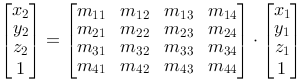
We use homogeneous coordinates from the beginning. This means that the general transformation matrix is a 4x4 matrix, and that the general vector form is a column vector with four rows.
P2=M·P1
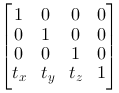
Translation
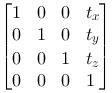 |
A translation in space is described by tx, ty and tz. It is easy to see that this matrix realizes the equations: x2=x1+tx y2=y1+ty z2=z1+tz |
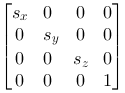
Scaling
|
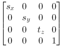
Scaling in space is described by sx, sy and sz. We see that this matrix realizes the following equations: x2=x1·sx y2=y1·sy z2=z1·sz |
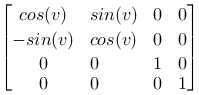
Rotation
Rotation is a bit more complicated. We define three different basic rotations, one around every axis.

Around the Z-axis 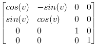
|
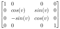
Around the X-axis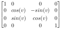
|
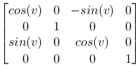
Around the Y-axis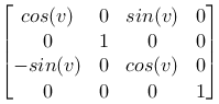
|
Geometry
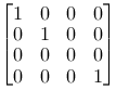
The identity matrix
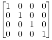
|
Again we can interpret it as:
|
Mirroring
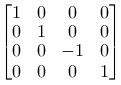
|
We can mirror the different planes by using scaling factor -1 on the axis that is placed normally on the plane. Notice the matrix to the left. It mirrors around the xy-plane, and changes the coordinates from a right hand system to a left hand system. |
Projection
|
So far we have only concentrated on moving points around in plane and space. Later we will worry about how we can depict space figures on a plane. It can be useful to notice that this can be done with a matrix operation. We can project a point orthogonal down into one of the main planes by using a matrix that scale the axis normally onto the plane with 0. The matrix to the left is a parallel projection down into the xy-plane. |
Compound operations
The reasoning we used in the plane can be transferred to space. Again we use the fact that we can make compound transformation matrices that represent compound geometric transformations.
In the plane the situation is well arranged and it is easy to follow the operations graphically. In space this quickly gets complicated, especially when we rotate. A quite demanding exercise, which often is repeated in graphical literature, is rotating around an arbitrary axis. We will not go through the reasoning for this here. It is seldom we need to construct so complicated transformations in our head when we write code. Usually we get away with simpler solutions if we make some rational choices in the description of the objects we want to represent.
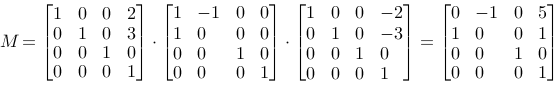
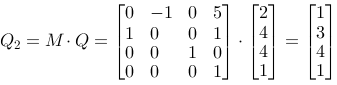
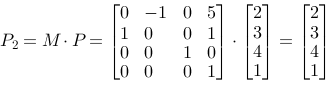
Let us use a simple example on rotation around an axis parallel to one of the main axes. We want to rotate the box on the figure 90 degrees around an axis that runs through P and is vertical on the xy-plane. The box has side edges of length 1. After the operation the point Q (2,4,4) should end up in Q2(1,3,4), and P(2,3,4) should remain in P2(2,3,4).

With our knowledge about transformations it should be a good strategy to:
- Move the point P in to the z-axis, the matrix T1
- Rotate around the z-axis, the matrix R
- Move the box back, the matrix T2
We remember from the chapter about 2D-transformations that we use the matrices in the opposite direction, and multiply from the left. We make the matrix M=T2·R·T1, and find Q'=M·Q and P'=M·P.
The figure or the coordinate system
To repeat in short: The reasoning above is based on the following:
We kept the idea about moving the figure. The order of the matrices is the opposite of the geometric logical order, of reasons that we discussed earlier for plane operations.
We can choose to reason in another way that goes better with the logic for the order of operations. It is the following:
- We move origin to the rotation axis, T2
- We rotate, R
- We move the origin back, T1
With this reasoning the order becomes: M=T2·R·T1 perhaps more logical.
In OpenGL
The functions in OpenGL:
  glLoadIdentity()
  glTanslatef(tx,ty,tz)
  glRotatef(v,x,y,z)
  glScalef(sx,sy,sz)
Notice that the f in the function names state that the parameters are floating numbers. There are integer number variants of the functions as well. Also notice that glRotate specify both rotation angle (in degrees) and rotation axis. A 30 degrees counterclockwise rotation around the z-axis looks like this:
glRotatef(30.0f,0.0f,0.0f,1.0f)
Rows and columns
Again we can choose if we want to the operations like P2=M·P, with P and P2 as column vectors or P2=P·M, with P and P2 as row vectors.
If we choose the last variant the respective base matrices become:
| Translation |
|
| Scaling |
|
| Rotation around the z-axis |
|
| Rotation around the x-axis |
|
| Rotation around the y-axis |
|
A lot of graphical literature describes transformations in this way. You can also study transposition of matrices in the module: Algebra.
